Over the last 12 months my posting has been dialled back, this isn’t for lack of wanting or ideas, mainly a lack of time and mental bandwidth. Reason being, I have been designing and implementing a new cloud platform (namely “STC” ↗) for my employer, Novosco - as with any new service or product this requires an element of discretion - but now is the time to let slip some of the detail on what makes the service tick!
Boilerplate caveat: any views or opinions expressed in this post or on this blog in general are my own and not that of my employer.
Requirement
Back when this project kicked off the brief was “make something scale-out, with dedicated kit per tenant in which they can manage their own virtualisation environment as if it were on-prem, BYO Licensing, BYO Backup, BYO Disaster Recovery”.
We like the idea of Bring Your Own X for this product

So, scale out, but dedicated hardware per tenant and we have to be able to spin these up at will, without much lead time and allow them to manage everything on their environment.
Initial Thoughts
The obvious solution for this kind of request is to go the whole “SDDC” road; SDS, SDN, the works, but then commercially it becomes ridiculous, plus SDN tech like NSX doesn’t allow for vmkernel traffic to be encapsulated, not that this is a blocker but, it doesn’t help - so maybe we can meet halfway?
If we have a SDS stack; ScaleIO, SpringPath, VSAN, …Maxta - just some hyperconverged node style SDS solution with a more traditional networking stack - could it be commercially viable and yet still meet the requirements we set out with?
Problems are obviously going to rear their heads when you have a dedicated compute environment that allows the ability to install BYO-anything on said environment, the focus very quickly becomes the shared components - in this case, networking.
I will go into the physical topology in another article as well as the decisions and math that led to it, just know that it is a 10/40GbE Spine and Leaf design with redundant ToR switching that is shared between customer environments.
Engineering
Generally when people want to separate customers that use the same networking kit; VLANs are the first port of call - but as a wise man once told me:
Friends don’t let friends build large L2 networks
This is easy to say, but why?
The L2 Problem
A few reasons, large L2 is certainly do-able, and a great many SPs do maintain and manage large L2 networks, so what’s the problem?
Loops
Looping and L2 networking are inseparable, there is always a pub argument to be had. Where multiple links to the same devices cause continuous looping of BUM (Broadcast, Unknown Unicast, Multicast) traffic.
There are of course remedies to this, MC-LAG, Bonding, Spanning Tree in any flavour will kill off the problems with looping on a multi-link switch to switch level - these of course come with their own limitations; link utilisation and load balancing being primary of which, with link aggregation of all flavours being more band-aid type solutions than “solving the L2 problem” - after all, you still need spanning tree even if you bond all your links to stop topological loops, and you still only have 4096 VLANs.
You can get into some pretty ugly config when you spin up a STP instance per VLAN (a-la MST/PVST) or you have a single instance and just lose half your bandwidth (or more).
But… What if the looping device only has a single link and doesn’t participate in spanning tree?
That’s right, you can have a loop on an STP enabled network from a device with only a single NIC. VMware’s vSwitching (both standard and distributed) are cases of such, or at least with VMs configured incorrectly they can be.
Read this KB ↗ - it is the harbinger of doom when it comes to L2 scenarios you never want to encounter.
Engineering around a situation like this is extremely difficult - it largely becomes T&Cs and user education. That is not to say it cannot be mitigated at least to a degree. Ivan at IPSpace ↗ makes some very good arguments with reference to VMware’s BPDU position and vSwitch implementation that will further help you understand the problem should you not see it so far (he has diagrams!).
I would also highly recommends his webinars on DC networking topologies ↗ on this topic if you’re interested in the engineering behind them.
Forged transmits, port security, BDPU filter and BPDU guard can all be used to mitigate these to a degree for your specific scenario but won’t stop the loops - the KB does a good job in dealing with these cases, as a service provider it is hard to determine if any of these cases are true unless you have visibility over the workloads operating on the environment, we do, thankfully - however, if you don’t there are behaviours and conditions you can view as “acceptable risks” should someone not follow the ToS.
- What is the maximum speed/pps my link can loop at (the link to the host’s speed)?
- What traffic volume can my spine uplinks/switch take?
- Is it acceptable that if the customer violates Terms of Use that their environment is “DoS’d” by BPDU Guard on the switches?
- Is it acceptable to request in the user manual if a customer wants to deploy an SSL-VPN appliance on the service they should contact the SP first for guidance?
In some cases it may be acceptable to the SP that when a customer violates the ToS their environment stability is at risk as long as it does not affect other customers using the shared components. Your position is entirely up to you but a combination of the above usually makes a good compromise.
Link Utilisation
Second to looping, there is link utilisation, which actually is where a lot of the solutions to looping actually lie. It also happens to be where most vendors have their secret-sauce flavour of link aggregation (Dell - VLT, Brocade - VCS, Cisco - FabricPath), there is of course an open standard for this, TRILL operates at layer 2/3 ↗ using a modified link-state routing protocol (IS-IS), but as of yet there is limited vendor support.
These all solve a Layer 2 problem, but with the caveat of proprietary tech, increased expense and eventually redundancy when an open standard takes over.
So, with that in mind, why use a large L2 “fabric” for your datacenter network - especially given it is a band-aide making Ethernet do things it was never meant to?
Limitations on Scale
We all know there is a VLAN limit of 4096, to most this might not seem like much of a limit and generally it isn’t - but when you are dealing with multi-tenancy and separation on a per-tenant level where they may have an allocation of 30-50 VLANs each, that has to do transit links, LANs, DMZs, storage, interconnects - it doesn’t add up to much when building out a scalable datacenter.
Operational Risk
A result of all the above, particularly loops is the risk involved from an operational standpoint - in a large scale L2 network there is always risk involved, Murphy’s law and all that. You just need a switch that is not participating in STP, or indeed one with the wrong bridge ID to case a world of pain - granted you can say that about almost any switching environment, but L2 problems tend to be quite catastrophic.
Solving the L2 problem with L3
You know what solves all of the above? Layer 3 - no loops (let’s ignore routing loops for now), fully utilised links from point to point when using a routed core with OSPF/BGP and ECMP selection with 5-tuple hashing for traffic distribution.
However, L2 adjacency is handy sometimes; like when you have a single tenant’s compute cluster split across racks (remember, L3 routed Spine/Leaf). We start off with a DC looking like this, but we get an order for 3 new nodes - normally we would have to waste the space left in Rack 1 to provide L2 adjacency when there is a L3 boundary between racks:
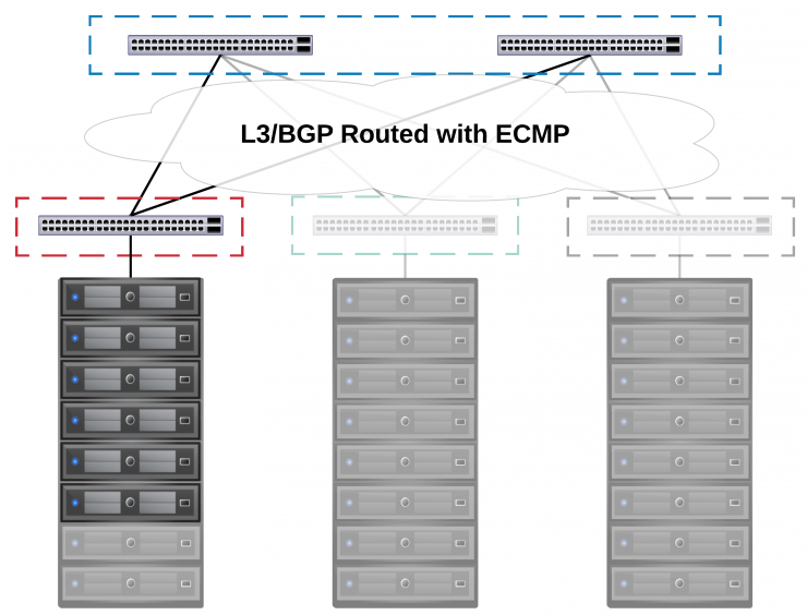
If this is the case the L2 networks need to be accessible in both racks, if you vMotion a VM from one to another or DRS does it, it still needs to be contactable by all other VMs in that broadcast domain.
So is there a way to get all the benefits as a service provider from a big L3 routed core network, with the ability to fully utilise all our links and have no loops - but still provide L2 adjacency and segregation to tenants across racks?
L2 over L3
Sure, let’s provide L2 over L3, there is a lot of tech out there to skin this particularly unlucky cat, most in use by telcos providing services like VPLS (typically using pseudo-wire tech AToM, GRE, L2TPv3) but sticking with a purely datacenter context the common options are VXLAN and EVPN.
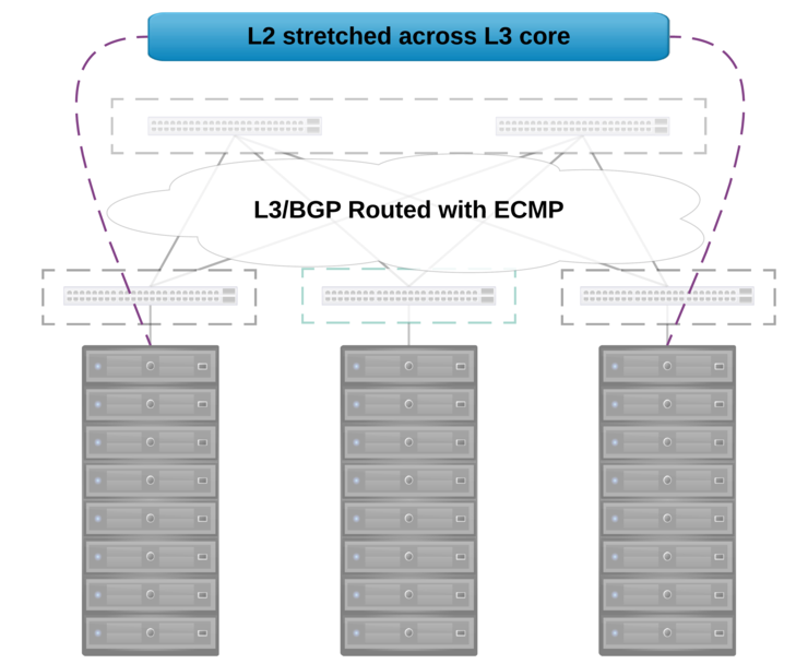
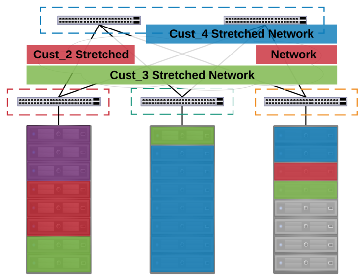
Overlays allow us to do some very cool stuff, take the instance above where we have an L3 boundary between racks, but we have a customer that wants to come on with 3 nodes, to do this across racks, we need to provide L2 adjacency to the customer LAN networks to allow the VMs to move around easily - if we encapsulate the L2 traffic and route it across the L3 core we can decapsulate the packet on the destination ToR switch and the L2 traffic will continue as if it were in the same rack as below.
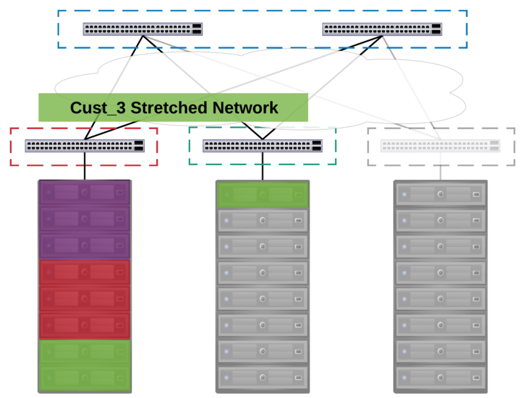
This of course can scale across multiple racks, as it is point to multi-point technology, allowing for us to stretch a given L2 network across a “limitless” number of racks, so we can mix and match customer nodes anywhere within the datacenter:
#TechnologyShowdown
So we want a L2 P2MP tech, to start off with eVPN - pioneered by Juniper, uses MP-BGP for control plane traffic as well as MAC and IP locality/distribution for an overlay technology (typically MPLS, PBB, VXLAN) - there are also multiple IETF RFC drafts for this standard, however the limited vendor support (Cisco and Juniper at the time) as well as lack of DC-rack class switches that these features are available on killed this tech off for the requirement.
VXLAN is an L2 encapsulation technology that will route packets over a standard L3 core network using UDP (with a larger MTU to allow for encap - typically 1600 bytes). VXLAN, has an official IETF RFC ↗ and has been implemented by multiple vendors (VMware, Arista, Cisco, Cumulus on switches with T2/T2+ chipsets, with many more coming like Mellanox and Dell) and very much seems to be the dominant choice for DC networking and such, was the logical choice.
It’s worth noting that VXLAN doesn’t have a discrete control plane - rather it can use an external controller or flood + learn.
Some networking vendors will only provide VXLAN tunnels if you have an external SDN-style controller, like Big Switch Networks, Dell and Cumulus. Generally this is not a problem when you have a single tenant infrastructure, you could use NSX-MH, BSN or an array of other controllers to provide intelligence about MAC locality and physical/host based VTEP endpoints.
This is not the case in a shared multi-tenant network because different vSphere environments means multiple integration points for MAC awareness and tunnel endpoints for any SDN controller. This feature was not provided by any networking vendor at the time in a commercially and operationally viable form.
So we had found another requirement, we couldn’t use a centralised controller at least none in their current forms but still needed P2MP.
Cumulus was ruled out at this stage due to a VXLAN tunnel down behaviour on loss of a single ToR switch when using MLAG ↗. This was apparently to stop traffic blackholing, being linux based, it is tricky I’m told to view status of individual links within a bond reliably.
Dell was also ruled out as while the DNOS (Force 10) switches at the time had a feature vxlan they didn’t allow for tunnels to be created via CLI, only controller based i.e. NSX - however, we have been told by our rep that this is no longer the case in DNOS 9.11 and arbitrary tunnels are now supported.
So that really only left Cisco and Arista - at the time Cisco only supported VXLAN on the 7k and 9k series switches, which didn’t lend themselves to Spine and Leaf (now of course they have the Nexus 5600) and the cost was prohibitive as well as some multicast routing performance challenges ruled out Cisco.
Thus, we arrived at Arista who allow for all of the above (they support CLI based flood + learn for MAC addresses and BUM traffic suppression) and have a good external controller story should we choose to move that direction in future - I’ve also been informed by our SE they now support L2 and L3 eVPN as a control plane for VXLAN.
The switches chosen were 48x 10GbE, 6x 40GbE for the leaf nodes and 32x 40GbE for the spine - I will get into link scaling in another article as stated above.
Providing an L3 core
We had our chosen overlay tech and vendor, what about the L3 core?
Typically in a spine and leaf you run a dynamic routing protocol like OSPF or BGP to distribute routes for all node interfaces to each other (VTEPs, loopbacks and P2P links for the spine/leaf fabric).
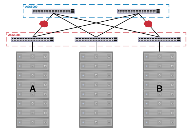
In this case, it was designed such that there was an AS per rack as well as a spine AS that all rack ASes peered with. This was chosen over a single AS for all leafs and spine as you can have instances in which traffic is dropped when a particular combination of links have an outage due to the default behaviour of BGP to prevent routing loops.
This can be overcome with allowas-in but it is more standard and safer to simply use a different ASN for each rack.
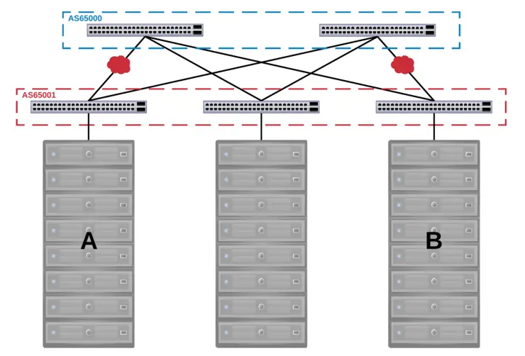
Like most things this is best described with a diagram or two, below you can see two ASNs, one for all leafs and one for the spine - the combination of link outages below would result in the traffic being unroutable due to BGP’s built-in loop prevention methods:
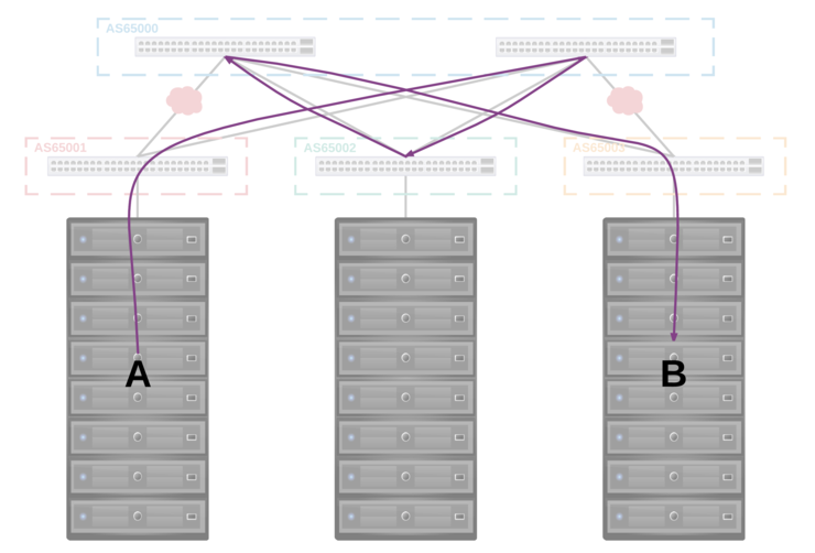
However, if we operate the network with an ASN per rack and an ASN for the spine we can see that the traffic can still be routed as there is no problem with the advertisement containing the same ASN as the one it is being advertised to:
iBGP was used to distribute the loopback and P2P interfaces to the other node at ToR as well provide redundancy should a leaf lose both uplinks to the spine and eBGP was used for the spine to distribute the routes learned from rack ASes to all other peered rack ASes - This provided VTEP visibility for all racks to each other as well as multiple routes to each destination which were then used for load distribution via ECMP.
The VTEP awareness across racks allowed for the creation of VLAN to VNI mappings that could traverse the spine.
It’s a given that to improve link utilisation you want a decent hashing algorithm for distribution of traffic, ECMP on Trident2 chipset based switches is by default 5-tuple (src + dest IP, protocol, src + dest port) - you will however need to enable explicitly multi-path BGP with:
maximum-paths [paths] ecmp [max ecmp paths per route to store in table]
Routing
So now we have an L3 core, we have L2 adjacency across racks - what about routing?
There is an interesting constraint with the Trident2 chipset - you can’t route between VLANs that exist on a VNI segment ↗ because it would require recirculation back into the chipset after decapsulation (how Arista achieves this with the T2) or a separate chipset specifically to route between VNI segments (Cisco Nexus).
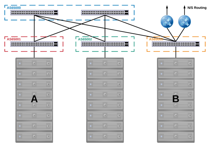
This was actually quite easy to solve - VLANs are stretched up to a pair of routers that come off the edge-leaf and provide all inter-VLAN routing and N/S traffic. Almost all of our customer traffic is E/W within the same VLAN and the traffic that was inter-VLAN is typically between DMZ/LAN and done on-host by a virtual firewall - anything else would traverse the links to the edge-leaf rack.
If a customer wished to use NSX however then routing could be done on the DLR within the hosts and save on traffic hairpinning as well as provide the value-added services from NSX.
This can also be achieved through the use of anycast gateway with VRFs on Arista switching where routing decisions are made at a ToR level, keeping the traffic within the rack so inter-VLAN routing does not have to traverse the spine or go to a centralised routing point as above. This has some obvious benefits, there are operational overheads involved here as well and at the time was not available from our chosen vendor that met all other requirements so we settled for the centralised routing option.
There is an excellent article on routing between VXLAN segments with MLAG and anycast gateway by Arista’s technical team here ↗. I will include one diagram from the article however:
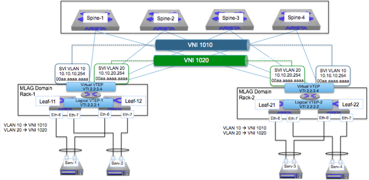
This shows the SVIs at the top of rack with the same IP, providing local routing decisions (as well as remote routing, done on the source ToR switch then sent over VXLAN) and vVTEPs for ARP suppression as well as broadcasts in large topologies. The article above is incredible and I highly recommend you read it if you want a good, in depth look at the exact packet flow in an environment like this.
Wrapping Up
So, after all that - you can see there is a lot to learn when it comes to DC networking, especially ones at scale with L3 involved, but that is not to say they are hard to maintain or operate.
Keep an eye out for articles in the near future on the maths behind why the particular switches were chosen and eventually ESXi networking config for VSAN over the encapsulated physical network.
Big thanks to Novosco (now Telefonica Tech UK) ↗ for allowing me to publish this article in as much detail as I have and for giving me the opportunity to architect such a solution, I couldn’t have done it without the help and input of the rest of the Hosted Platforms team as well as the broader Novosco team!
Why not follow @mylesagray on Twitter ↗ for more like this!