Based on my last post, you’ll understand some of the challenges that are faced with traditional approaches to datacenter networking so let’s get into the high-level conceptual design here of how we might solve one of these problems. Most service providers have or are at least familiar with using MPLS for customer segregation in a WAN scope as I alluded to in my previous datacenter networking article. What we want to do is simplify the provisioning and distribution of subnets to a customer’s virtual environment, all the way up to the WAN.
Conceptual Design
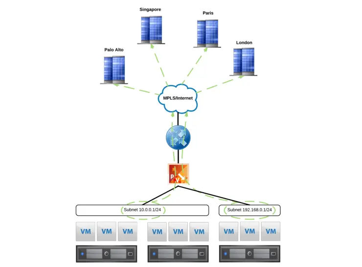
The endgame here is - if we add a VM, or indeed a Logical switch to NSX that all the other sites in the MPLS for that customer know about it without us having to touch a thing. This gives us our first step in achieving a fully automated networking platform.
Typically, static routes are added to customer virtual routing domains (VRFs) that tell the MPLS what subnets exist behind each site if they’re not directly connected to the customer provided equipment (CPE). You can of course use dynamic routing with a router behind the CPE, but again - manual configuration of Switch Virtual Interfaces (SVIs), not as robust as automating it all.

Above we can see the desired outcome, a Logical Switch is added to NSX for a particular customer and that subnet is automatically distributed, from the host, into the customer VRF and to all of that customer’s sites on the MPLS.
Logical Design
With the concept in mind, let’s map out what this looks like logically, I had done up a diagram recently for Mark Brookfield (virtualhobbit) ↗ on how such a solution might look for his lab so i’m going to take liberty and put it in here:
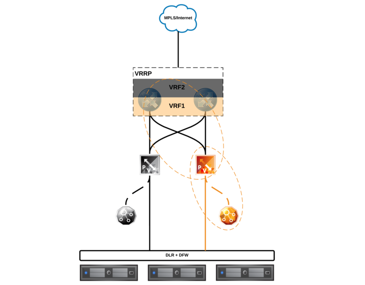
At the bottom, we have our hosts, with the Distributed Logical Router and Distributed Firewall (DLR/DFW) on top - they are connected to the Edge Services Gateway (ESG) via a Logical Interface (LIF) - the DLR control VM can be seen off to the side (it’s not a data-plane component, just control-plane for routing updates and such).
There is an ESG in the data path between the DLR and the upstream routers/CPE which provides the customer VRFs and gateway to the WAN.
Physical Design
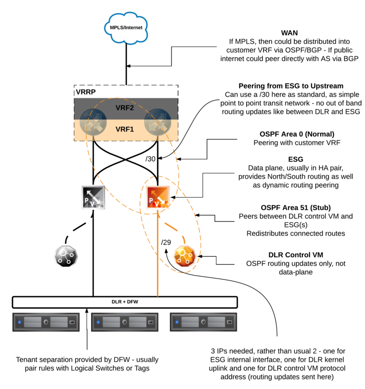
This is where the fun begins - i’m going to start with a diagram that you can refer back to as we go through these concepts below:
Let’s start at the bottom as that’s where our routing decisions will largely take place and where new routes will originate from.
Distributed Logical Router
When you add Logical Switches to the DLR and you have OSPF/BGP peering northbound to the ESG enabled, these subnets will automatically be advertised upstream - this is essential in allowing an infrastructure like this to scale.
The DLR provides in-kernel routing between VMs, if VMs are resident inside a single host and are on different subnets, they will route entirely inside the kernel, thus cutting out any northbound traffic leaving the host.
If VMs are in different subnets and are also on two separate hosts, obviously, traffic will have to leave the source host. The packet is encapsulated in a VXLAN header and will be delivered and routed in the kernel on the other host, still appearing as if it came from the same L2 segment as it originated from - thanks to the encapsulation.
This also saves on excessive North/South traffic on the Top of Rack (ToR) to Spine switches by simply pushing the traffic to the NSX VTEP VLAN, being switched at the ToR and then back down to the other host. In itself this alone greatly helps with oversubscription ratios on ToR -> Spine links due to reduced N/S traffic and can mean racks can be made more dense owing to higher oversubscription ratios.
The DLR is also the place where VLAN to VXLAN bridging takes place in the kernel if you bridge any VXLAN segments to physical VLANs (In this case, vDS PortGroups) then it will be done on-host at line rate.
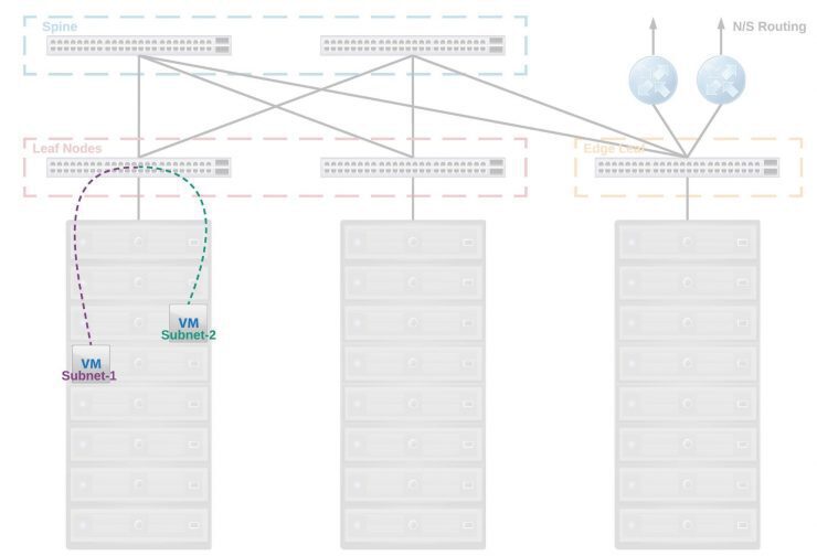
Below we can see a typical spine and leaf that utilises routing at the edge of the network:
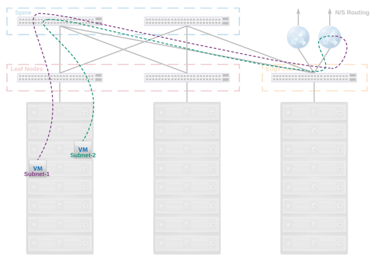
With NSX in play; rather than needing to be routed centrally and transit across a number of switches and routers, thus consuming bandwidth on the Spine and Leaf interconnects and suffering an increased Round Trip Time, the packets are encapsulated by the VTEP on the source host, pushed to the ToR, switched and sent down to the host where that packet is destined and then routed in the kernel. See how the data path no longer traverses the Spine and Leaf interconnects for the same operation?
This is of course possible if you use VRFs and anycast gateway on your ToR switches - the packet would be sent to the ToR, routed, then sent to the corresponding host - I mentioned this in my previous DC networking article towards the end. This approach does however introduce a lot of complexity into the physical network and some very specialist configuration and debugging skills. It is operationally very heavy, high touch for subnet changes, complex and carries with it the appropriate risk. Not to mention you need relatively high-end switches. This approach also does not allow for some nice features that NSX adds (multi-site firewall/policy rules, failover, integrations with other high level virtualisation aware solutions, etc).
DLR to ESG

There are a few operations that go on between the DLR and the ESG - there will need to be a point-to-point transit network (typically a Logical Switch) that is a /29 subnet to provide N/S connectivity from the kernel LIFs to the default gateway or routes advertised by the ESG.
Typically when I deploy dynamic routing between the DLR and the ESG I will use OSPF - the ESGs do come by default with two OSPF areas (`` - a “normal” area and 51 - a “NSSA” type), the NSSA will point towards the DLR and will allow the DLR to advertise routes into the ESG - area 0 is then pointed northbound on a transit link (usually a physical VLAN), to the upstream routers/CPE and will provide routing advertisements to the customer’s VRF in the MPLS switch/router.
I’d like to highlight here the distinction between a /30 and a /29 between the DLR and the ESG - there is a lot of misinformation out there about this particular scenario and I want to clear it up.
If you are using a dynamic routing between the DLR and the ESG you must use a /29 subnet for your transit network, this is because while the DLR and ESG both have a LIF in same subnet - this is only used for data-plane traffic. The DLR kernel module’s LIF itself does not listen for dynamic routing advertisements. That is the job of the DLR Control VM as in the above diagram.
The DLR Control VM listens for and sends OSPF and BGP routing advertisements - it is not in the data-path but it still needs to be on the same subnet as the DLR and ESG LIFs to be updated with, and make, the routing advertisements - given a /30 subnet only has 2 usable addresses, that is obviously no good as we need one for the ESG LIF, one for the DLR kernel LIF and one for the DLR control VM interface.
A point to point logical switch with dynamic routing between the ESG and the DLR should like like the below:
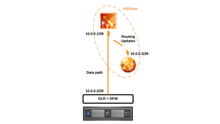
If however, you aren’t using dynamic routing between the DLR and the ESG, you can use a /30 as the DLR Control VM doesn’t need an interface in the subnet in order to update the DLR control plane.
Edge Services Gateway

The ESG provides in-path routing, NAT and L7 data services like Load balancing, SSL-VPN, IPSec, L2VPN. It is the boundary between the two OSPF areas as stated above and provides all N/S traffic in and out of a customer environment, as such, it is important to deploy them as a HA pair.
ESGs have the ability to use Equal Cost Multi-Pathing (ECMP) to statefully select traffic paths to/from both the DLR and northbound routers - this has the advantage that if a customer is pushing more than 10Gbps of traffic, you can scale out an ESG cluster and provide better performance across multiple paths.
The ESG can be configured to advertise a default route to the DLR (default-information originate) as well as redistribute routes learned statically, as connected, or via OSPF or BGP. The ESG is where we will focus the configuration of the routing into the customer VRFs on the upstream routers.
Upstream Routing

So this is not in NSX-scope but is a critical component of this architecture - in order to have any changes we make at an NSX level distributed to customer sites and provide multi-tenancy we need to have the upstream routers support VRF, this means we can have multiple routing tables with overlapping subnets on the same router but are kept separated and distinct.
To make sure there are no SPOF on the upstream the design would mandate a stack or pair of devices that are VRRP capable - this means that if a single device fails the other assumes its identity with a virtual MAC address and all traffic will continue to flow normally.
The link between the ESG and this upstream routing will also be a point-to-point /30 link - this differs from the transit link between the ESG and the DLR you’ll remember.
The reason behind this difference is that while the DLR Control VM is not in the data-path, the ESG is. As such, the ESG LIFs can also send/receive routing updates as well as normal traffic so there is no need for an “out of band” routing address.
To advertise routes learned from NSX via the ESG the router must be configured such that OSPF area 0 is configured within the customer’s VRF and is peered with the ESG meaning any routes learned via OSPF on the router will be added to the routing table in the customer’s VRF. This is actually the same process that you would use even if you are not using MPLS and rather are routing upstream to another Autonomous System via BGP and your routers are part of the public internet.
Conclusion
You should be able to see from the above that implementing a solution like this has great value in automation terms, leading to more reliable, consistent environment configuration that will scale well, in the next article I will be covering the actual implementation of the above design and demoing the capability.
Why not follow @mylesagray on Twitter ↗ for more like this!